
Pursue HDMI EDID Bugs
Today I tried to track down the EDID (“Extended display identification data”) bug on my STi7111 (Golden Media 990CR ) spark box. EDID is needed to detect the display attached to the set-top box. On the newer STi7105 based boxes this works quite good. But on the STi7111 based spark boxes there is a hardware issue.
During EDID query the frame-buffer driver prints out the following warning message:
stmfb: first EDID byte (255) is corrupt, attempting to fix..
stmfb: Invalid extension header checksum block0
stmfb: first EDID byte (255) is corrupt, attempting to fix..
stmfb: Invalid extension header checksum block0
stmfb: first EDID byte (255) is corrupt, attempting to fix..
stmfb: Invalid extension header checksum block0
stmfb: first EDID byte (255) is corrupt, attempting to fix..
stmfb: Invalid extension header checksum block0
stmfb: EDID Read Error, setup safe EDID
stmfb: Setting Safe EDID
So I decided to take a look at the hardware and do some test. Because EDID is needed for a working HDMI-CEC set-up. The EDID information is stored inside an EEPROM on the Television/Montor. The EEPROM is accessed by the STB via an I2C bus.
The result looks a little bit chaotic isn’t it?
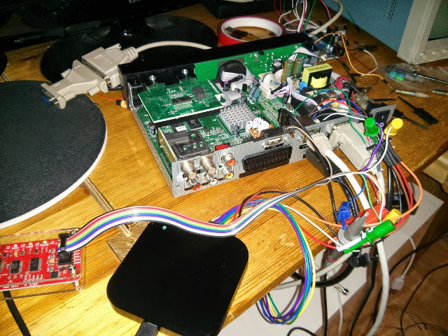
The image shows the set-top box, a salea logic16 logic analyser and a DP Bus Pirate. The salea logic analyser is to listen to I2C communication between the various loose ends. Before we can access the HDMI connector and the I2C EDID data lines we have to remove the Ethernet board. This is achieved by removing just one screw and lifting the complete Ethernet board.
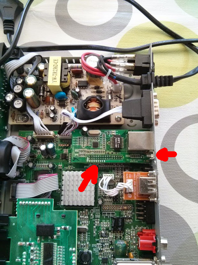
After removing the Ethernet board it looks like this:
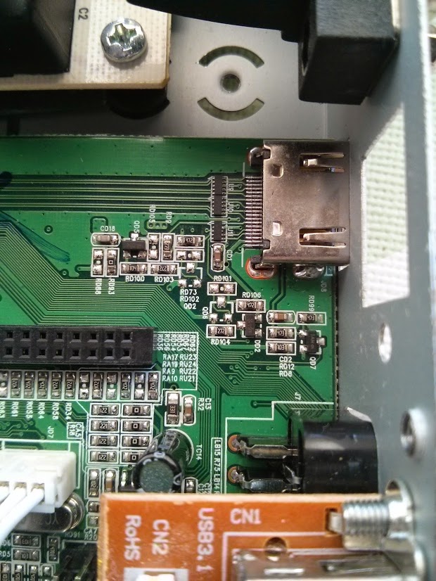
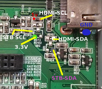
For debugging purposes I soldered some wires to the related components. There are two types of I2C bus involved. The one from HDMI which is a 5V type and the one from the STB which is at a 3.3V level. So the not applied components seems to form a level shifter. If I attach an HDMI monitor to the STB I can see transfers from STB to an EEPROM on the board which response with 0xFF in all bytes. But no communication over HDMI. Because the loose ends are not connected.
With an attached bus pirate to the HDMI I2C bus I can readout the EDID information from the attached monitor.
HiZ>m
1. HiZ
2. 1-WIRE
3. UART
4. I2C
5. SPI
6. 2WIRE
7. 3WIRE
8. KEYB
9. LCD
10. PIC
11. DIO
x. exit(without change)

(1)>4
I2C mode:
 1. Software
 2. Hardware

(1)>1
Set speed:
 1. ~5KHz
 2. ~50KHz
 3. ~100KHz
 4. ~400KHz
The i2c sequence to read data from the EEPROM have to define a start address where we want to read from:
I2C>[0xa0 0]
I2C START BIT
WRITE: 0xA0 ACK
WRITE: 0x00 ACK
I2C STOP BIT
With this we start from address 0.
So now lets read 128 byte of EDID data:
I2C>[0xa1 r:128]
I2C START BIT
WRITE: 0xA1 ACK
READ: 0x00  ACK 0xFF  ACK 0xFF  ACK 0xFF  ACK 0xFF  ACK 0xFF  ACK 0xFF  ACK 0x00  ACK 0x04  ACK 0x72  ACK 0x30  ACK 0x02  ACK 0x01  ACK 0x00  ACK 0x00  ACK 0x00  ACK 0x08  ACK 0x15  ACK 0x01  ACK 0x03      ACK
 0x80  ACK 0x33  ACK 0x1D  ACK 0x78  ACK 0x0A  ACK 0x90  ACK 0x85  ACK 0xA3  ACK 0x58  ACK 0x53  ACK 0x9F  ACK 0x26  ACK 0x0F  ACK 0x50  ACK 0x54  ACK 0xBF  ACK 0x6F  ACK 0x00  ACK 0x71  ACK 0x4F  ACK     0x81
  ACK 0xC0  ACK 0xD1  ACK 0xC0  ACK 0xB3  ACK 0x00  ACK 0x81  ACK 0x80  ACK 0x01  ACK 0x01  ACK 0x01  ACK 0x01  ACK 0x01  ACK 0x01  ACK 0x02  ACK 0x3A  ACK 0x80  ACK 0x18  ACK 0x71  ACK 0x38  ACK 0x2D      ACK
 0x40  ACK 0x58  ACK 0x2C  ACK 0x45  ACK 0x00  ACK 0xFD  ACK 0x1E  ACK 0x11  ACK 0x00  ACK 0x00  ACK 0x18  ACK 0x01  ACK 0x1D  ACK 0x00  ACK 0x72  ACK 0x51  ACK 0xD0  ACK 0x1E  ACK 0x20  ACK 0x6E  ACK     0x28
  ACK 0x55  ACK 0x00  ACK 0xFD  ACK 0x1E  ACK 0x11  ACK 0x00  ACK 0x00  ACK 0x1E  ACK 0x00  ACK 0x00  ACK 0x00  ACK 0xFD  ACK 0x00  ACK 0x38  ACK 0x4C  ACK 0x1E  ACK 0x4B  ACK 0x0F  ACK 0x00  ACK 0x0A      ACK
 0x20  ACK 0x20  ACK 0x20  ACK 0x20  ACK 0x20  ACK 0x20  ACK 0x00  ACK 0x00  ACK 0x00  ACK 0xFC  ACK 0x00  ACK 0x4D  ACK 0x32  ACK 0x33  ACK 0x30  ACK 0x48  ACK 0x44  ACK 0x4C  ACK 0x0A  ACK 0x20  ACK     0x20
  ACK 0x20  ACK 0x20  ACK 0x20  ACK 0x01  ACK 0x56
NACK
I2C STOP BIT
We do not need any pull-ups power set-up for the Bus Pirate because the bus is already pulled high by the STB. And due to the fact that I2C only pulls level to low we need no adjustment for 3.3V and 5V.
With some editor regular-expression magic we can form a python snippet to create a binary EDID file we can analyse later.
import struct
edid_txt = [ '0x00', '0xFF', '0xFF', '0xFF', '0xFF', '0xFF', '0xFF', '0x00',
             '0x04', '0x72', '0x30', '0x02', '0x01', '0x00', '0x00', '0x00',
             '0x08', '0x15', '0x01', '0x03', '0x80', '0x33', '0x1D', '0x78',
             '0x0A', '0x90', '0x85', '0xA3', '0x58', '0x53', '0x9F', '0x26',
             '0x0F', '0x50', '0x54', '0xBF', '0x6F', '0x00', '0x71', '0x4F',
             '0x81', '0xC0', '0xD1', '0xC0', '0xB3', '0x00', '0x81', '0x80',
             '0x01', '0x01', '0x01', '0x01', '0x01', '0x01', '0x02', '0x3A',
             '0x80', '0x18', '0x71', '0x38', '0x2D', '0x40', '0x58', '0x2C',
             '0x45', '0x00', '0xFD', '0x1E', '0x11', '0x00', '0x00', '0x18',
             '0x01', '0x1D', '0x00', '0x72', '0x51', '0xD0', '0x1E', '0x20',
             '0x6E', '0x28', '0x55', '0x00', '0xFD', '0x1E', '0x11', '0x00',
             '0x00', '0x1E', '0x00', '0x00', '0x00', '0xFD', '0x00', '0x38',
             '0x4C', '0x1E', '0x4B', '0x0F', '0x00', '0x0A', '0x20', '0x20',
             '0x20', '0x20', '0x20', '0x20', '0x00', '0x00', '0x00', '0xFC',
             '0x00', '0x4D', '0x32', '0x33', '0x30', '0x48', '0x44', '0x4C',
             '0x0A', '0x20', '0x20', '0x20', '0x20', '0x20', '0x01', '0x56' ]

f = open('edid.bin', 'w')

for i in edid_txt:
	bin = int(i,16)
	f.write(struct.pack('B',bin))

f.close()
For EDID analysis I’ve used to tool “read-edid” which contains a tool called “edid-decode”.
$ edid-decode edid.bin
Extracted contents:
header:          00 ff ff ff ff ff ff 00
serial number:   04 72 30 02 01 00 00 00 08 15
version:         01 03
basic params:    80 33 1d 78 0a
chroma info:     90 85 a3 58 53 9f 26 0f 50 54
established:     bf 6f 00
standard:        71 4f 81 c0 d1 c0 b3 00 81 80 01 01 01 01 01 01
descriptor 1:    02 3a 80 18 71 38 2d 40 58 2c 45 00 fd 1e 11 00 00 18
descriptor 2:    01 1d 00 72 51 d0 1e 20 6e 28 55 00 fd 1e 11 00 00 1e
descriptor 3:    00 00 00 fd 00 38 4c 1e 4b 0f 00 0a 20 20 20 20 20 20
descriptor 4:    00 00 00 fc 00 4d 32 33 30 48 44 4c 0a 20 20 20 20 20
extensions:      01
checksum:        56

Manufacturer: ACR Model 230 Serial Number 1
Made week 8 of 2011
EDID version: 1.3
Digital display
Maximum image size: 51 cm x 29 cm
Gamma: 2.20
Supported color formats: RGB 4:4:4, YCrCb 4:2:2
First detailed timing is preferred timing
Established timings supported:
  720x400@70Hz
  640x480@60Hz
  640x480@67Hz
  640x480@72Hz
  640x480@75Hz
  800x600@56Hz
  800x600@60Hz
  800x600@75Hz
  832x624@75Hz
  1024x768@60Hz
  1024x768@70Hz
  1024x768@75Hz
  1280x1024@75Hz
Standard timings supported:
  1152x864@75Hz
  1280x768@60Hz
  1920x1152@60Hz
  1680x1050@60Hz
  1280x1024@60Hz
Detailed mode: Clock 148.500 MHz, 509 mm x 286 mm
               1920 2008 2052 2200 hborder 0
               1080 1084 1089 1125 vborder 0
               -hsync -vsync
Detailed mode: Clock 74.250 MHz, 509 mm x 286 mm
               1280 1390 1430 1650 hborder 0
                720  725  730  750 vborder 0
               +hsync +vsync
Monitor ranges: 56-76HZ vertical, 30-75kHz horizontal, max dotclock 150MHz
Monitor name: M230HDL
     Has 1 extension blocks
Checksum: 0x56
The result looks quite good isn’t it? One of the next step would be to connect the loose ends. Or trying to write useful information to the on board eeprom.
blog comments powered by Disqus